|
Building
DML's T19 105mm Howitzer Motor Carriage |
 |
Building
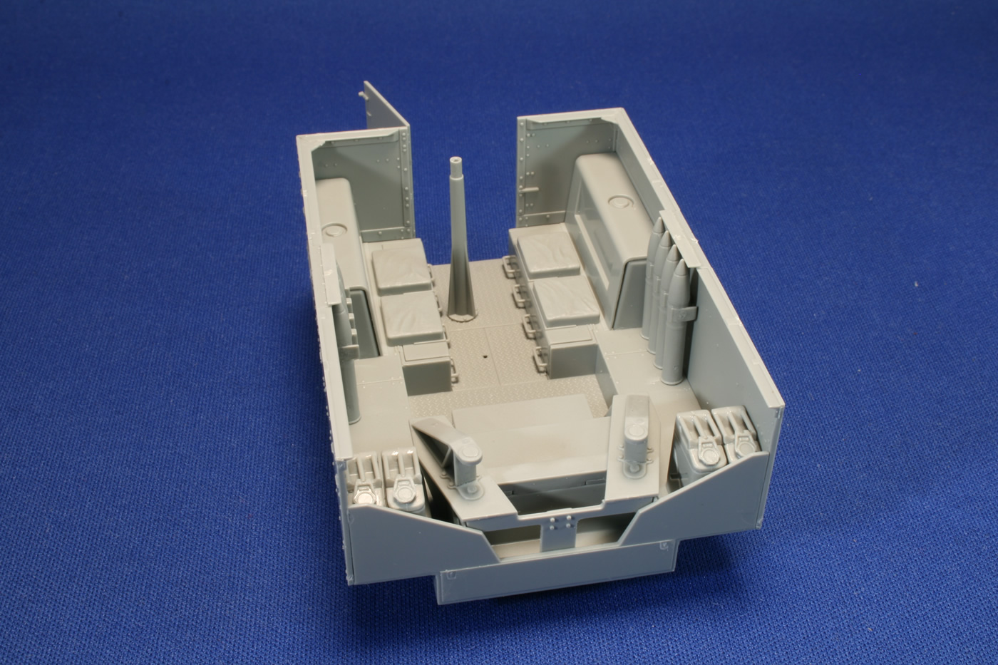
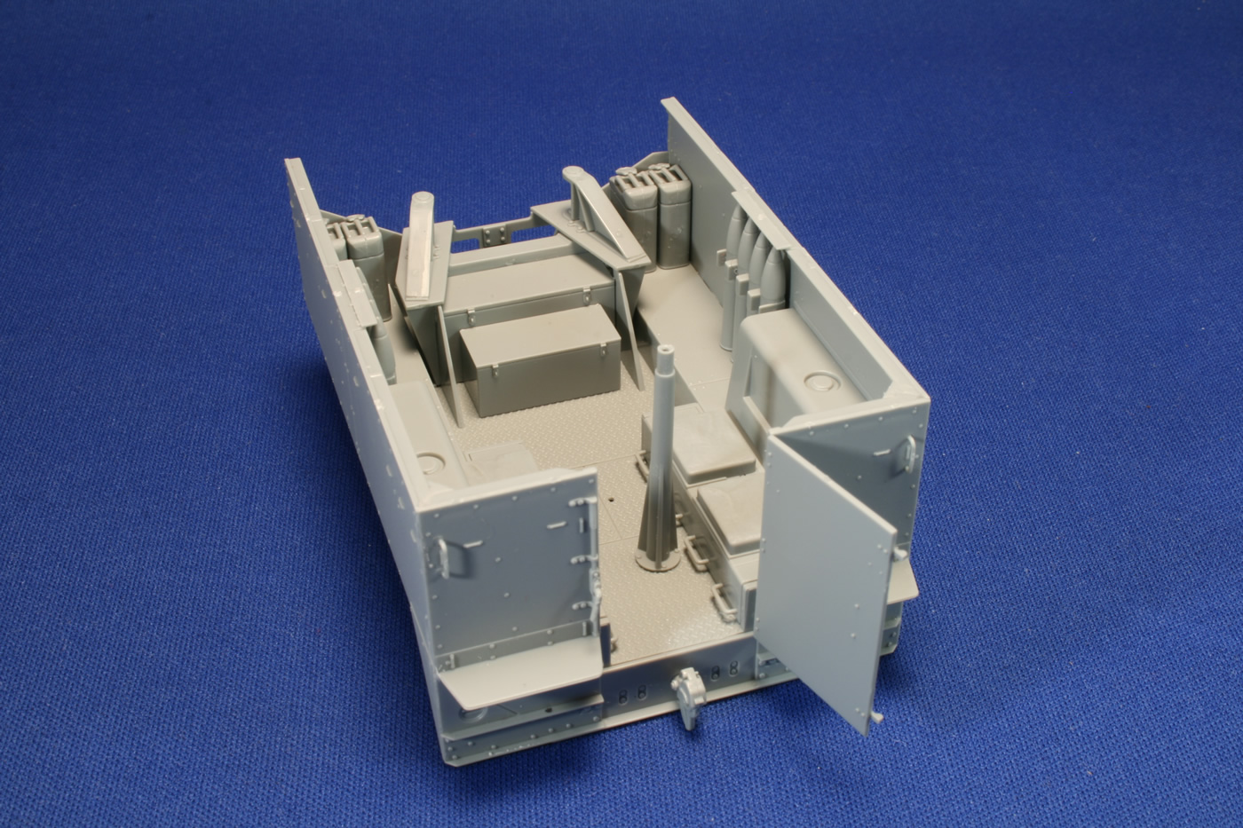
the Fighting Compartment
The instructions call for a.30 caliber machine gun mounted on the pedestal (mostly stateside training images), but there's a photo in Zaloga's armored artillery book of the .50 cal in use in Tunisia. The weapons sprue includes a .50, so there you go. I set aside the four-round clips of 105mm ammo to paint separately. Another departure from instructions: I glued the pair of adapted trail mounts (as assembled from G18 and G9/G8) to the floor mounting in the compartment, rather than to the gun carriage. The reason for this was to make it easier to paint the larger subassemblies. When I got the mounts glued in place I slid the gun into position for a dry fit and all was good.
The instructions would have you put the rear door handle (part C33) on the inside of the door, but actually it belongs on the locking bar on the exterior rear wall to the left of the door opening. You'll see a small hole that is ready to accept the locating pin on the handle. The representation of three aiming stakes on some sort of board is a stake short and a board too many. In reality, the stakes were secured to the top of the fighting compartment wall by a pair of large clasps. There doesn't appear to be any sort of shelf to support them, at least not to the extent that the kit part suggests (there are short plates above the 105 ammo rounds to protect the fuses). Perhaps the stakes are resting on some sort of canvas sheath? In any event, this is one of those problematic pieces for armor modelers: you don't know if it's exactly accurate or not (and what happened to the fourth stake?) if you use the part, you have to paint the stakes white and red stripes; If you leave the stakes off the vehicle, as though they were set out in the field, you should scratchbuild some clasps. One thought I had is to slice the stakes off on either side of the clasps that are molded around them, and then hollow out the center portions to open up the clasp. So there are a few options for you. At this point, I want to keep my options open on the placement of the aiming stakes and staff for the barrel brush, so they will be tended to separately (a typical situation when I have a few conflicting diorama ideas in my head as I'm building). Introduction Building the Chassis Building the Tracks Building the Cab Building the 105mm Howitzer Building the Fighting Compartment Ready for Paint Painting and Weathering References -tss- | ||||||


 |
 |
 |
 |
 |
 |
 |
 |
 |
 |
 |
 |
|