|
Building
DML's T19 105mm Howitzer Motor Carriage |
 |
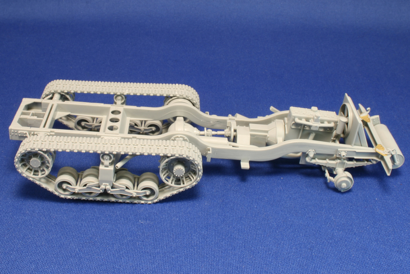
Building the ChassisThe build starts to go wayward in Step 1B, where parts A8 and A9 seem to be transposed, but neither part looked exactly like the pictured image. After switching them back and forth a few times I lost track of which was which and trusted that any misapplication would be unnoticeable. The other assemblies of the front and rear axles, engine, and radiator go well. The controversial "bulged" tires are still the only option in the box. But the intricately molded and cleanly cast drive sprocket and rear idler parts are a joy. I've built all available, and these are infinitely more realistic than Monogram and Tamiya; cleaner and more user friendly than Tank WorkShop; and included in the kit, unlike K59, the dethroned champ. I departed from the instructions at Steps 2 and 3, which address the bogey suspensions and road wheels. I built the suspension units, but set aside the road wheel assemblies until time came to put on the tracks, because the wheels straddle the joined two-part track sections. It appears that the bogeys used on the T19s did not have the hole through the center of the housings. Best evidence of that is a photo on page 15 of Zaloga's U.S. Armored Artillery in WWII. In Step 4, work on the chassis frame hit a momentary snag with the instructed use of the double coil springs for the rear suspension area. In reality, these were not seen on T-19 as they were an outgrowth of manufacturing modifications after the last T-19 was built. According to Hunnicutt, the T19 HMC was built from January to April 1942. The initial work order for the modified single coil spring-loaded idler was made in late November 1942, and the double coil idler spring (the type included in the DML T19 kit) was not standardized until mid July 1943. It's possible some vehicles could have been retrofitted with the intermediate single spring version or the double coil spring. But if you want to build one as typically fielded, you will want to replace parts C34 and C35 with parts C43 and C44 and omit the springs, parts A21 and A22. (Since I had already glued 34 and 35 in place, I had to fill the square holes in the pieces that accept the coiled spring.) I also set aside the idler axles (parts D31) and other doodads (C29, C30, A15 and A16) until I was ready for the tracks.
In Step 5, the engine is added to the chassis, and this would be a good time to do some detailing if you opt to have the hood opened (easy to do with the score lines in place on the undersides of the parts). The power assist and drive shaft for a winch are called out as optional parts, but you can leave them off since the T19s appear to have only the front ditching roller and no winch. The axles are added as well as the suspension units (in my case, minus the road wheel units). Even the much vaunted slide mold technology can't provide a satisfactory solution for the two-part roller cylinder. A seamless roller was beyond the reach of Tamiya and appears to be out of DML's grasp, too. Instead of dividing the cylinder horizontally, DML has halved it vertically, so there is still a seam to be smoothed. The end of the exhaust pipe requires a slightly hollowed-out cap, so you'll need to tend to the seam at that joint as well. At the opposite end of the pipe, watch carefully where it connects to the engine manifold; my parts wouldn't stay in contact and I had to wedge the end of a paintbrush in there until the glue had set. Some photoetch gussets are added to the bumper. When attaching the bumper/roller assembly to the frame it would be good to dry fit carefully and observe any alignment issues after gluing. Introduction Building the Chassis Building the Tracks Building the Cab Building the 105mm Howitzer Building the Fighting Compartment Ready for Paint Painting and Weathering References -tss- |
 |
 |
 |
 |
 |
 |
 |
 |
 |
 |
 |
 |
|