|
Building
the Academy M7 Priest |
 |
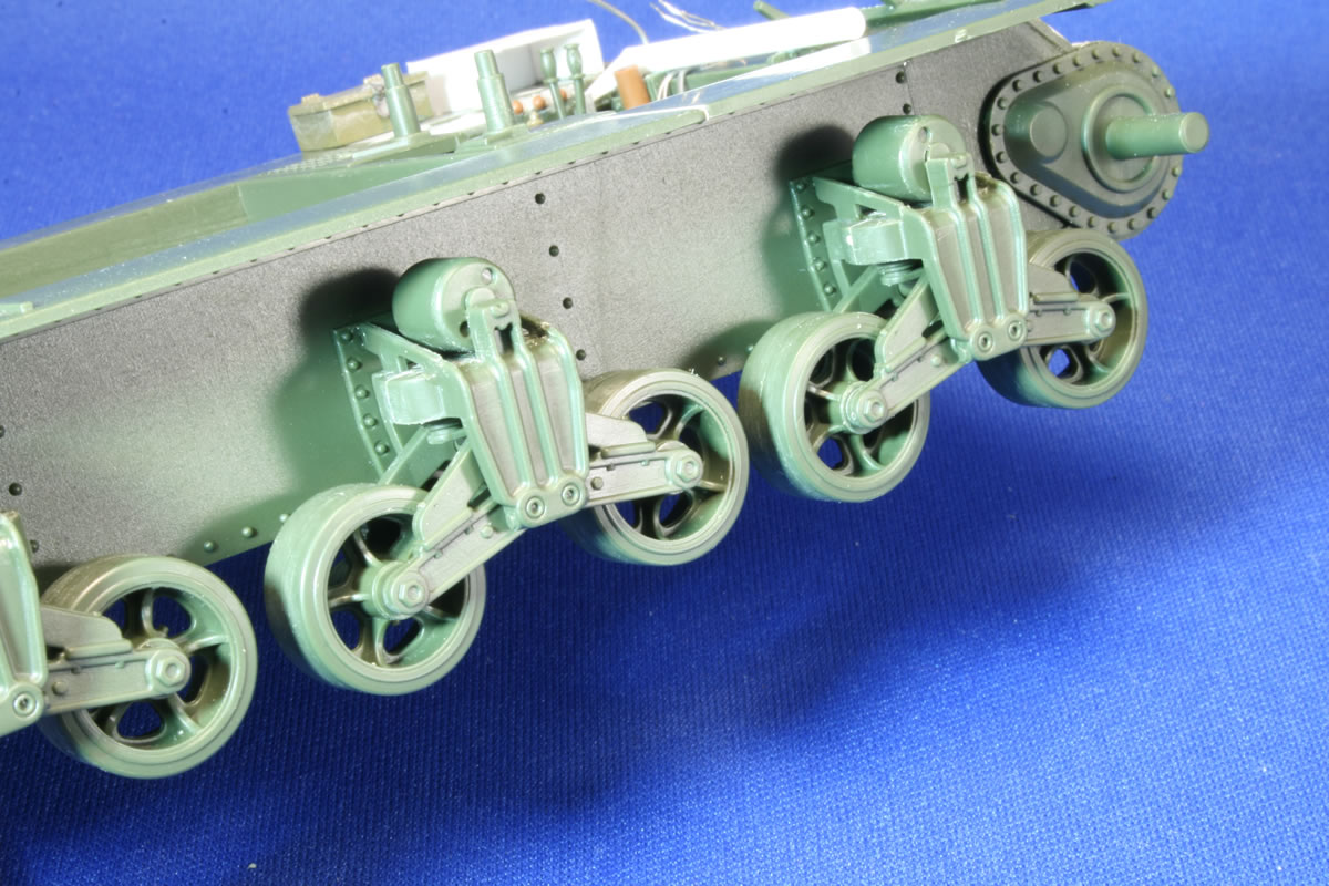
| Suspension
and Lower Hull There are no big problems with the Academy hull and suspension units. The lower hull contains the bolts seen on the early and intermediate Priests. You need to plug the hole on the bottom floor that must have been designed for a yet-to-be-produced motorized version. There are a couple sponson details left over from the M3 Lee that need to be removed carefully as the sponson is exposed on this open-topped vehicle..
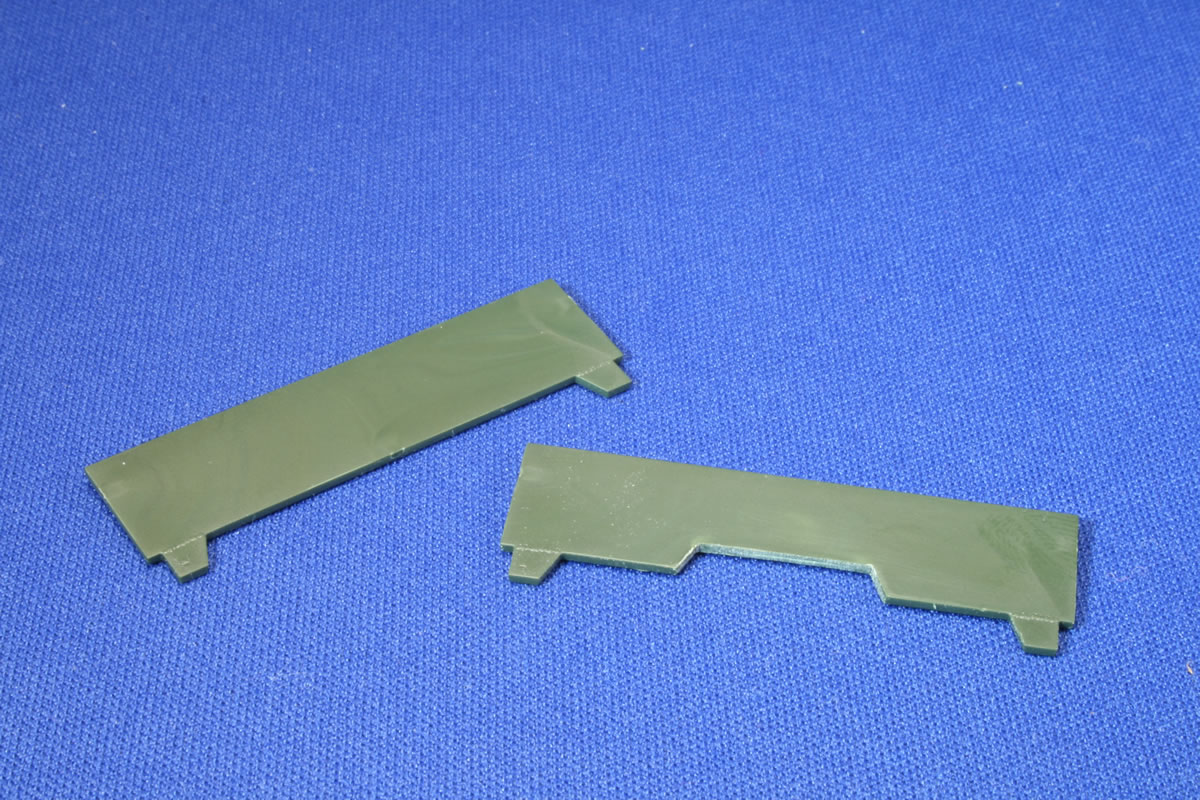
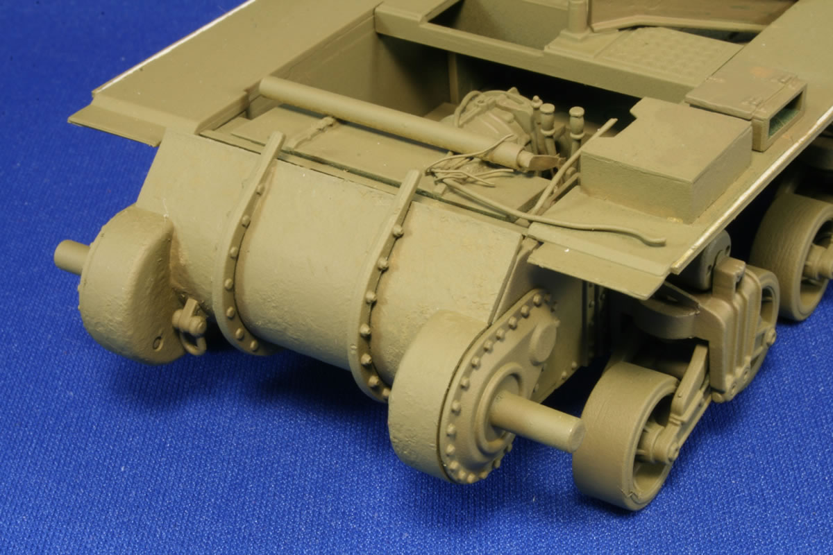
If you are going to use photo etch for the fenders, you'll want to remove the fenders from parts H7 and H8 before gluing them to the hull. The kit does not call for building the rear hull wall until step 9, where it is attached to the upper deck, and I followed the instructions in this instance. But now is a logical time to note that the wall comes with separate engine compartment doors you can leave open if you wish to detail the interior. The kit provides box air cleaners, but I opted to use a pair from Italeri's M4A1 to present the earlier round version. To get them to fit between the rear wall and the overhang wall, I had to scrape off the raised mounting rectangles. I used the Eduard photo etch eyebolts rather than the thicker kit parts. (This is one of those detail toss-ups: thicker but properly rounded kit parts or thinner but flat photo etch, or scratchbuilt wire pieces. I vacillate between the options depending on my ambition.) NEED PHOTO OF REAR PLATE ASSEMBLY Also be aware that if you do not use the kit's rear fenders (parts B21 and B22), you will have a gap to attend to when you mount the deck and rear wall to the lower hull. But we'll get to that later.
Don't forget to drill out the "keyhole" for the engine starting crank. It is a little tricky to get the correct shape. I used a very thin bit in a pin vise to drill two holes next to each other, and then a larger bit to drill the larger center hole. If you don't get it quite right, well, that's what big tarps are for. The kit comes with the distinctive fish tail exhausts that can be easily seen when the overhang is correctly notched. The exhausts are one piece (C17) that mounts to the underside of the engine deck, but they are too high to present themselves properly. I used some scrap plastic between the deck and the part to move them lower and into view. The Priests had screens on this back area that aren't easily visible, but there was a sheet metal deflector that I fashioned out of some aluminum.
Introduction |
 |
 |
 |
 |
 |
 |
 |
 |
 |
 |
 |
 |
|