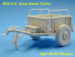
| M10
U.S. Army Ammo Trailer |
 |
|
Tiger Model Designs is gaining a reputation for filling in some significant holes in the AFV modeling arsenal. In 2002 they came out with an M8 ammo trailer, and this was joined by an M10 trailer kit in 2003. Trailers were an integral, if unglamorous, part of the U.S. inventory during WWII. With the exception of the trailers found in old Tamiya and Italeri jeep kits, and a few European resin kits, they've been pretty much ignored by the modeling industry. Through these trailers and the release of 105mm and 155mm ammo loads, TMD has seen an opportunity to help modelers and dioramists render a more complete picture of the mechanics of warfare.
While I've used a lot of aftermarket kits to spruce up vehicles or build figures, this is the first resin kit I've built of a complete vehicle. It presents some of the challenges unique to building resin kits (fixing warped parts and limited working time with superglue) as well as very complex assemblies, where fewer parts would not compromise the finished product (sometimes less is more). So it's really geared toward the skilled intermediate or advanced modeler. The Kit
There are over 80 parts, including lengths of plastic rod, wire, and thin solder. Some very fine chain is used for the back tailgate, and a sheet of lead foil for creating straps (no buckles are included, however). The resin parts are formed from a compound that produces soft castings with some flexibility to them, which is important with the very thin pieces used for the wheel stand. If they were rigid, they would easily snap in two. But the softer resin also means there is less resistance when trimming the pieces from the casting blocks, so it's easier to carve off too much from the pieces. Many of the parts are cast flush with the blocks, so there is no margin for error. A fresh blade in your hobby knife, a steady hand, and good lighting are necessary for this kit. Aside from the challenges posed by the casting methods, the parts themselves have exceptional detail and crispness. Some problems were encountered on individual pieces, where worn or torn molds allowed some hollowed parts to be filled or produced minor bumps that needed to be trimmed down. And while the parts are carefully packaged, some pieces did have delicate pieces that were broken off. It's always a good idea to carefully remove pieces from their plastic bags, as broken parts might be inside. I had to contact TMB to replace the trailer frame and rear gate, as they have little tabs that were broken and missing from the bag. Joe Bakanovic quickly responded to my email with replacement parts. Another trailer feature, the lunette unlocking lever ring, was broken from the frame neck, but I found in the bag. Ultimately I decided to replace that with a ring of wire. The eight full-sized pages of instructions are reasonably clear and straightforward, with the building process broken down into 16 steps. There are no decals included, but you could pull some bumper codes from spare decals or get trailer markings from Archer Fine Transfers. Construction Most steps in the instructions begin with the word "Carefully remove…" and this is the order of the day with this kit. The first significant challenge was faced in Step 1, which is the construction of the two-piece frame and trailer body. The body had a large pour block on the bottom, and the side walls were bowed inward. The frame on which the body rests was also warped. A quick dip in boiling water (two to three seconds) is recommended in the instructions. The problem with this, as far as the body goes, is straightening the side walls while not deforming the floor of the body. It took me several attempts to get the walls reasonably square, but the bottom rear corners of the piece did lose some of their form, which became more apparent when fixing the piece to the frame (part #2), which also had to be boiled and squared. There was also a lot of sanding that had to be done to the pour block on the bottom of the body, even though what remains is hidden by the frame. I tried to carve the edges of the block down so it would fit within the frame, and ended up losing some of the square edge on the corners of the body. It took me over an hour just to accomplish the first step of construction. I was not satisfied with the way the body and the supporting frame of piece #2 joined at the rear of the trailer, but since I plan to use it with the gate open, this will be hidden. Steps 2 and 3 are relatively simple, adding the electrical box and handbrakes (which can be fixed in released or applied positions).
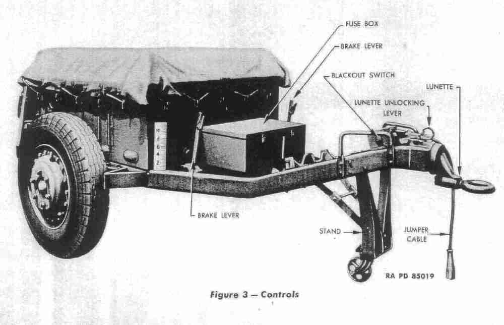
Things became a bit more difficult in Step 6, which begins the construction of the lower section of the jack-stand. I had to use my hobby knife to drill out the holes in the caster wheel and its retainer in order to get the .03" plastic rod axle through. Part #E-3 was deformed by the mold, and had to be cleaned and drilled out in order to slide the resin rod #E-5 through it, which in turn is sandwiched into the frame #E-4. The jack-stand is designed to be built so it can be collapsed (for traveling) or extended (for static position). Because my finished locking lever resembled the template example, but not exactly - some of the bends within the wire were not precisely uniform - I wasn't sure if this might have an impact on the final assembly of the frame of the jack-stand, because I did not know how precise the pieces for the rest of the stand would fit, or if there was any tolerance for even the slightest error. Added to this, in Step 7, is the fact that you need to attach the frame arms (D-1) that hang from the wire lever to two pieces (D-2) that extend (and slip off of) pins on the frame, by means of another small length of .03" plastic rod - which loosely slips through #E-3. So you are essentially trying to attach and glue five pieces that have no fixed points, while not knowing if you do successfully fix one side that the other side will be properly aligned due to the bends in the wire lever. The stand subassembly from Step 6 is supposed to slip into the retaining holes in the trailer frame, and thus be able to swivel up and down while you're gluing the pieces above. But I found that the resin rod #E-3 was too long and the subassembly would not insert into the retaining holes without bending the rod. So I trimmed away some of the circular wall around the retaining holes until I was able to insert the subassembly. Sensing that I would quickly be driven mad by trying to attach the aforementioned framing pieces to another unanchored piece, I glued the subassembly in an extended position. This made it somewhat easier to attach pieces D-1 and D-2, but only somewhat. This rapidly became an exercise in finger positioning and patience, being mindful of not bending or breaking off the delicate brake levers. Construction of this section took over an hour, during which time I gave considerable thought to the advantages of offering two sets of pieces to build either a folded or extended stand. Because you must glue the final assembly in one position or the other, any advantage of building it as a workable unit is quickly lost. And since the folded version requires precise building in order to get the frame to "lock" onto the lever release, I can only imagine how many attempts would be necessary to accomplish this small feat. Step 8 details the attachment of handles and the gooseneck hitch to the front end of the frame. The attachment stub on the lunette (#F-1) is too large to fit into the gooseneck. From tech manual photos of the real trailer, it appeared that just a small amount of the stub on the lunette is seen, so I trimmed it down and glued it to the gooseneck. You can attach the gooseneck to the frame in either a "high" or "low" position. My plans are to use this with Tamiya's M8 HMC, which requires the "low" position for hitching up to the back of the AFV. Make sure you know the vehicle that will be pulling your trailer and you've accounted for the height of its towing hitch before you attach the trailer's gooseneck. The fuse box, in which fuses for arming the ordnance cargo were carried, is attached in Step 9. The box has a large casting plug on its side that needs to be sawn off - carefully - so as not to mar the lid of the box. There are slight corner extensions on the side of the box without the plug, but these are not on the side with the plug. Rather than trying to sculpt them on, I just carved them off the other side, since they do not appear in the tech manual photos. It would have been easier if the casting plug had been on the bottom of the box, rather than the side. Step 10 finishes off the bottom side of the trailer, including the axle and protective cover. In Step 11, the brake drums are attached to the axle ends. There are casting plugs on the backsides of the drums and it's easy to carve too much off, losing the lip of the drum. Before affixing the drums, however, you need to attach brake cable receivers (parts B-1) to the drums. One was broken on the resin carrier, but I found the tab in the bag and glued it to the receiver. The cable is fashioned from snips of solder. The next step includes attaching the very thin tire guards to the frame. One of mine broke in two as I tried to remove if from the carrier. In this step you are also supposed to attached the wheels. I left these off to paint separately. Note that the tires have non-directional mud and snow pattern tread (similar to that seen on most U.S. AFV kits like jeeps and halftracks), rather than the civilian tread with the zigzag pattern around the circumference of the tires as was most often seen on these trailers during the war.
Seventeen tie-down cleats are attached to the trailer sides in Step 15. You have the option of resin cleats, or fashioning your own out of wire with the template included in the kit. I opted for the resin pieces, but quickly found that the ends that need to be attached were rounded and didn't provide much contact surface for gluing. I nipped them down with my knife. It appears you should glue them to the edge of the plates that are molded onto the trailer sides but the contact area is not well defined, so I positioned them right above the plates. Step 16 addresses the optional addition of 31 tie-downs throughout the lower interior of the trailer through which straps secured ammo loads. If you have a full load you can easily ignore this step and just wrap some lead foil straps around the contents to secure them. Construction took about 10 hours over the course of several days. Conclusion As I said, this little kit is really for the more experienced modeler with strong nerves, nimble fingers, and eagle eyes. Even with its complexity being arguably a case of overkill, it builds up - with care - into a very nice model. TMD has two ammo load kits available for their trailers. While their 105mm load has been temporarily pulled from the market because of some accuracy problems with the ammo bundles, their 155mm load set is correct and provides 18 rounds and 9 charges in metal canisters. AFV Club also has a set of 155mm and 203mm rounds and charge canisters, but note that their decals are for post-WWII ordnance. Verlinden also produces 105mm and 155mm howitzer rounds; their 75mm howitzer rounds have been out of production for several years, unfortunately. While designated as an ammo hauler it can be safely assumed that GIs would fill it with anything they needed to carry with them that couldn't find a space on or in their vehicle. So jerry cans, sidearms ammo, bedrolls and haversacks, etc. certainly found their way into any trailers.
-tss- |
 Tiger
Model Designs
Tiger
Model Designs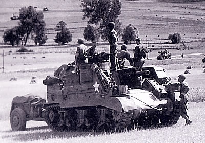 The
M10 trailer was designed to be towed by M7 Priests, M8 howitzer motor carriages,
and 105mm Shermans, as well as other vehicles. As noted in the instructions, the
M10 was produced by three companies from 1942 to 1945, and there were slight differences
in the finished pieces from these manufacturers. According to TM 9-2300, February,
1944, the trailer was designed to carry 117 rounds of 75mm howitzer ammo, 44 rounds
of 105mm ammo, or 16 rounds of 155mm.
The
M10 trailer was designed to be towed by M7 Priests, M8 howitzer motor carriages,
and 105mm Shermans, as well as other vehicles. As noted in the instructions, the
M10 was produced by three companies from 1942 to 1945, and there were slight differences
in the finished pieces from these manufacturers. According to TM 9-2300, February,
1944, the trailer was designed to carry 117 rounds of 75mm howitzer ammo, 44 rounds
of 105mm ammo, or 16 rounds of 155mm. 

 |
 |
 |
 |
 |
 |
 |
 |
 |
 |
 |
 |
|