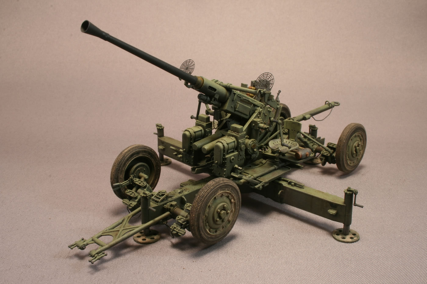
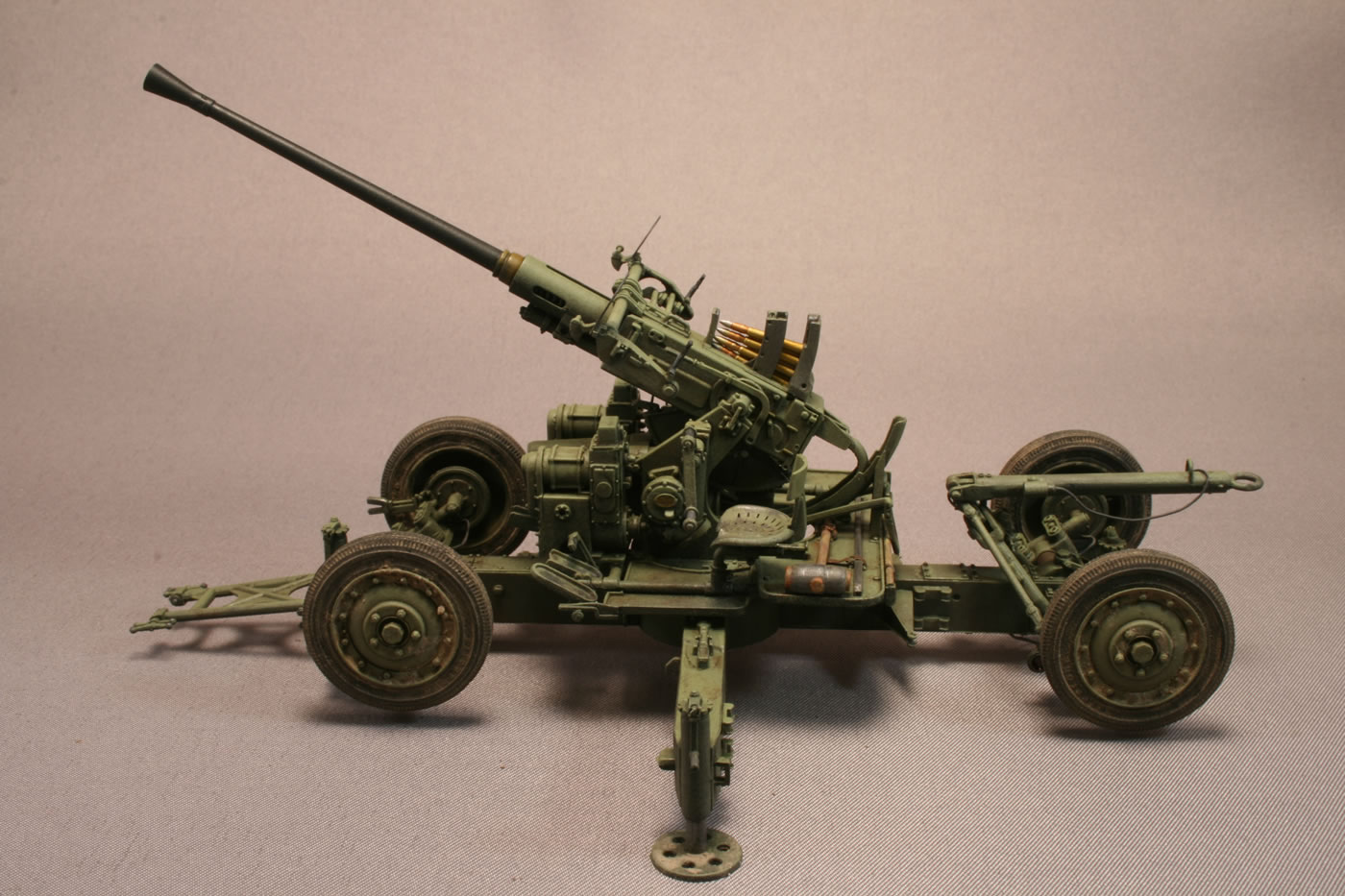
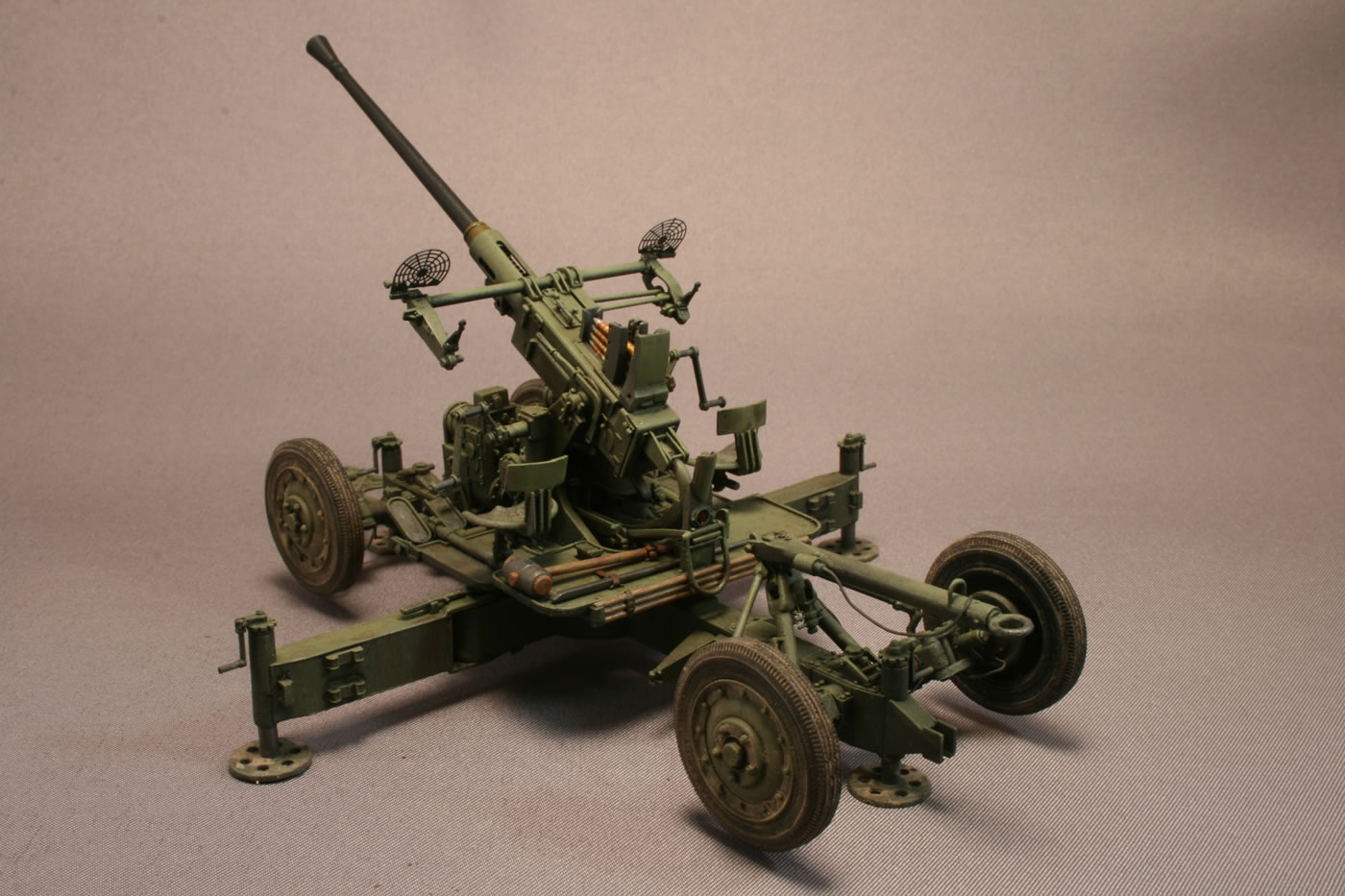
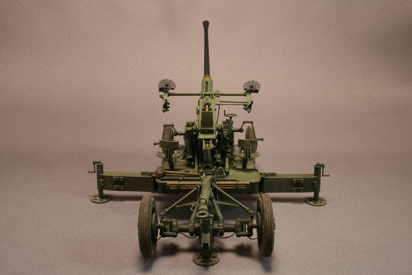
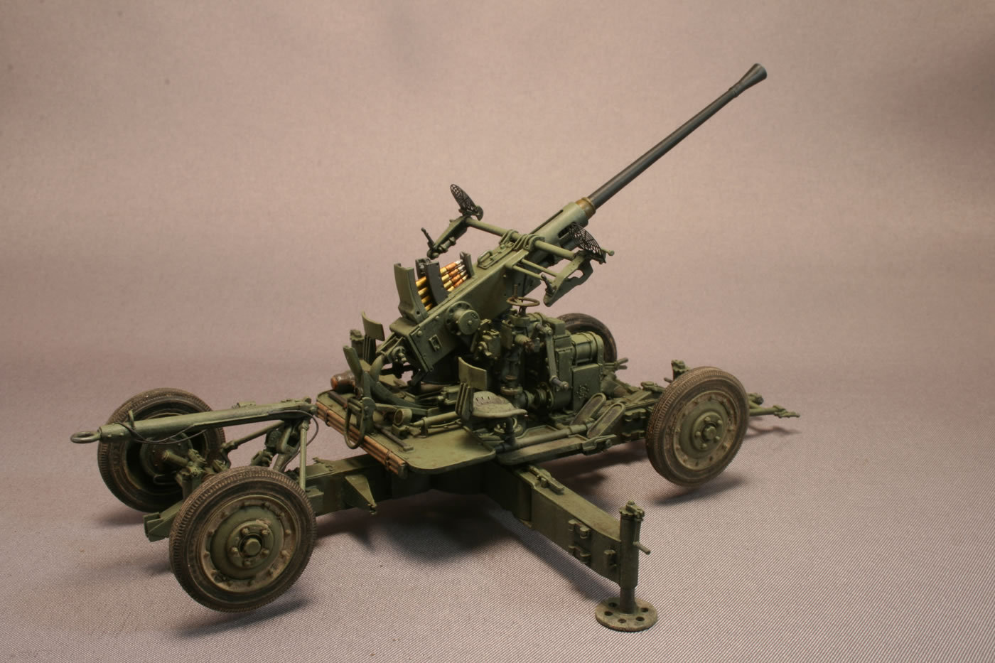
| M1 40mm Bofors Anti-aircraft Artillery |
 |
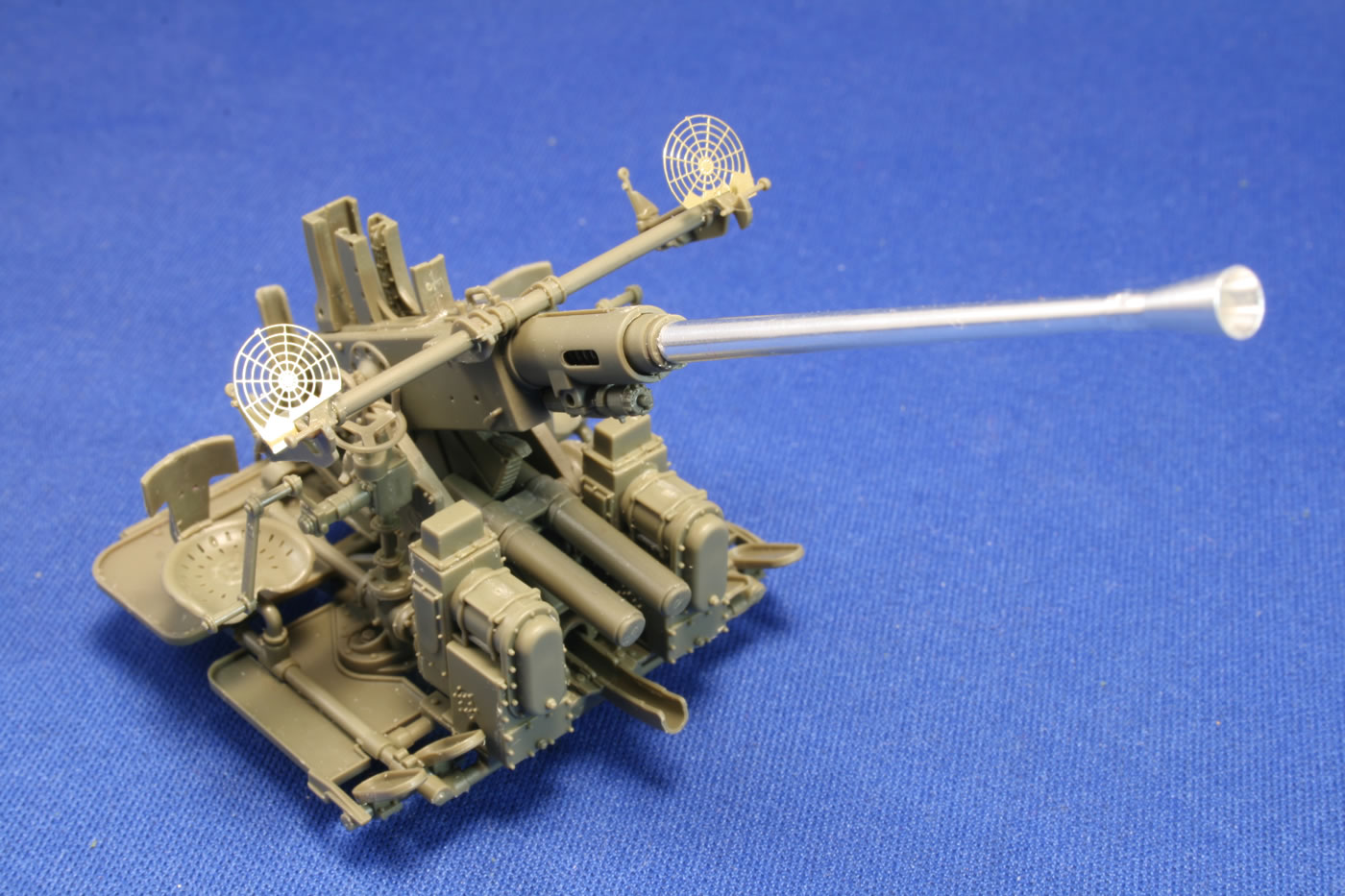
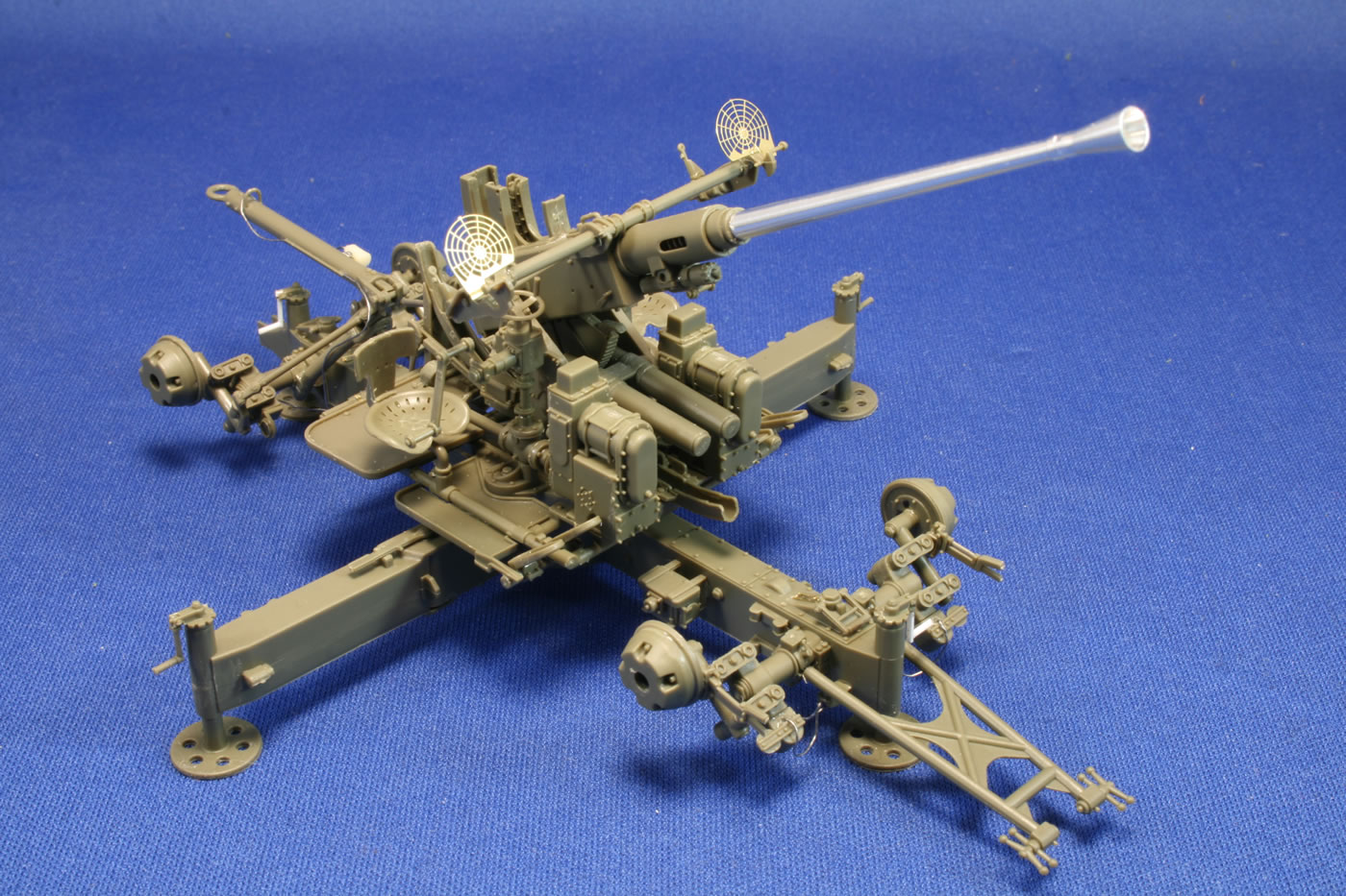
 AFV
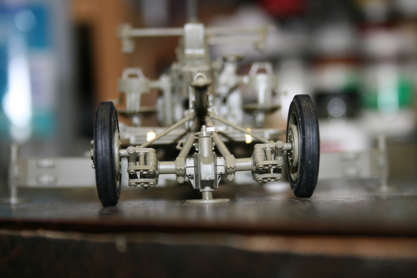
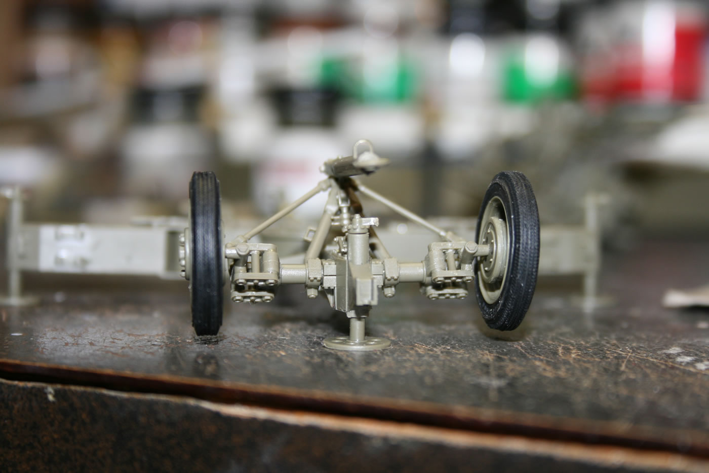
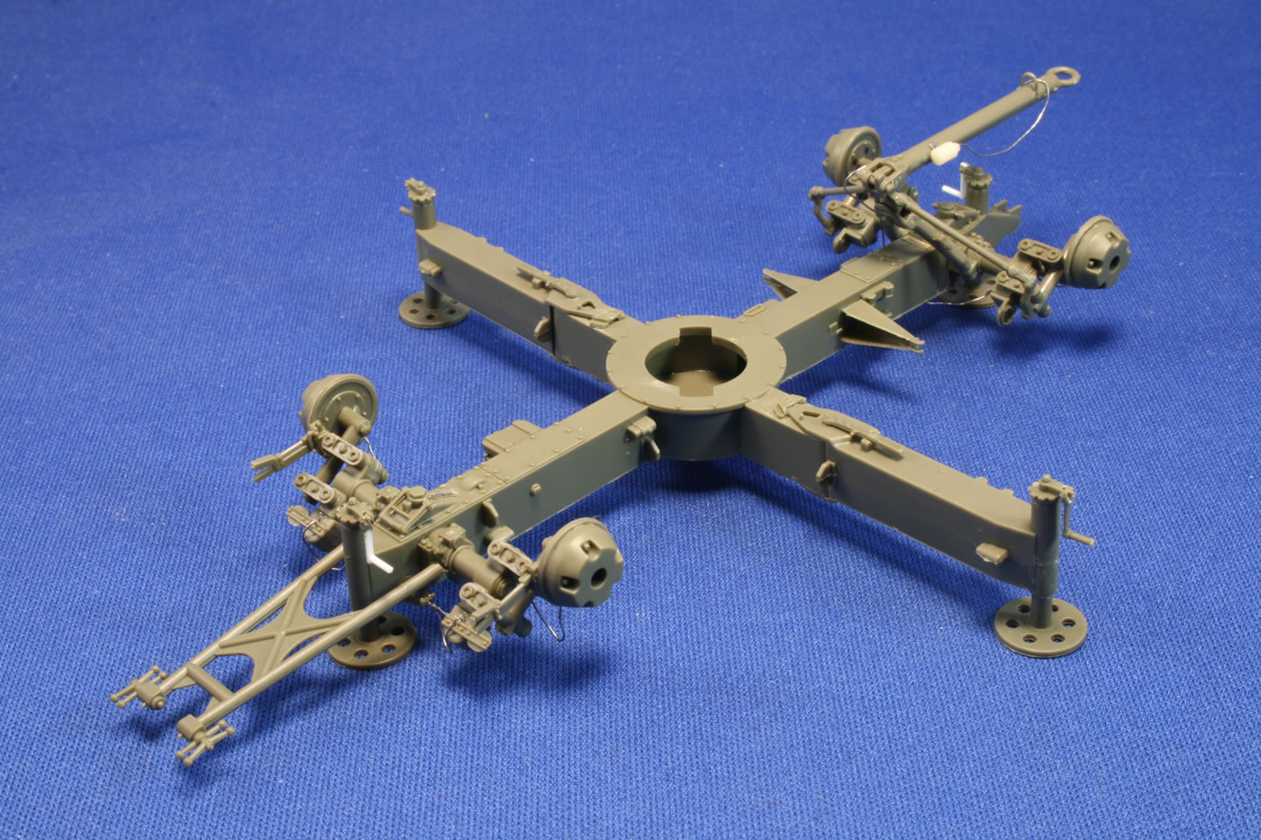
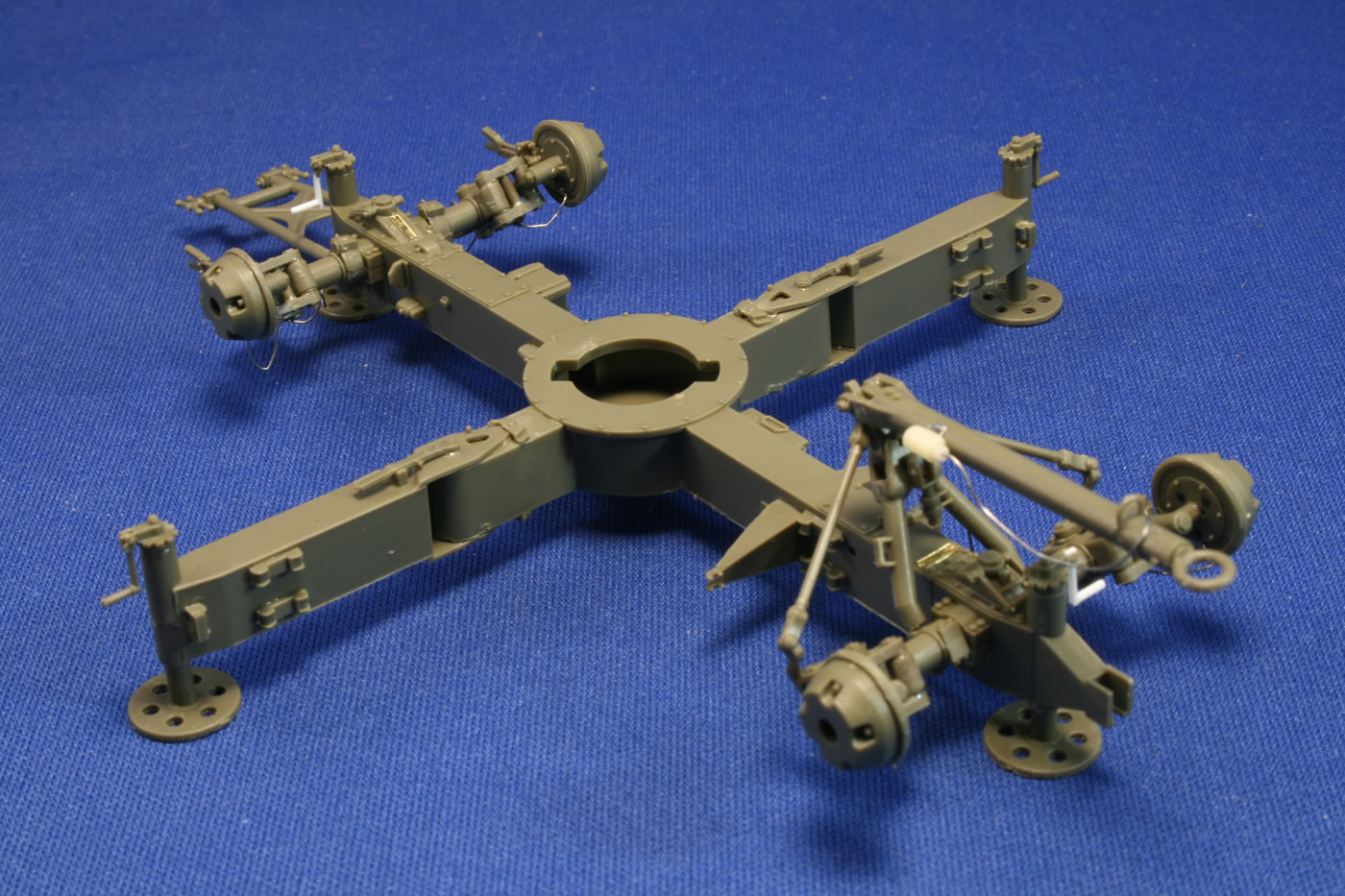
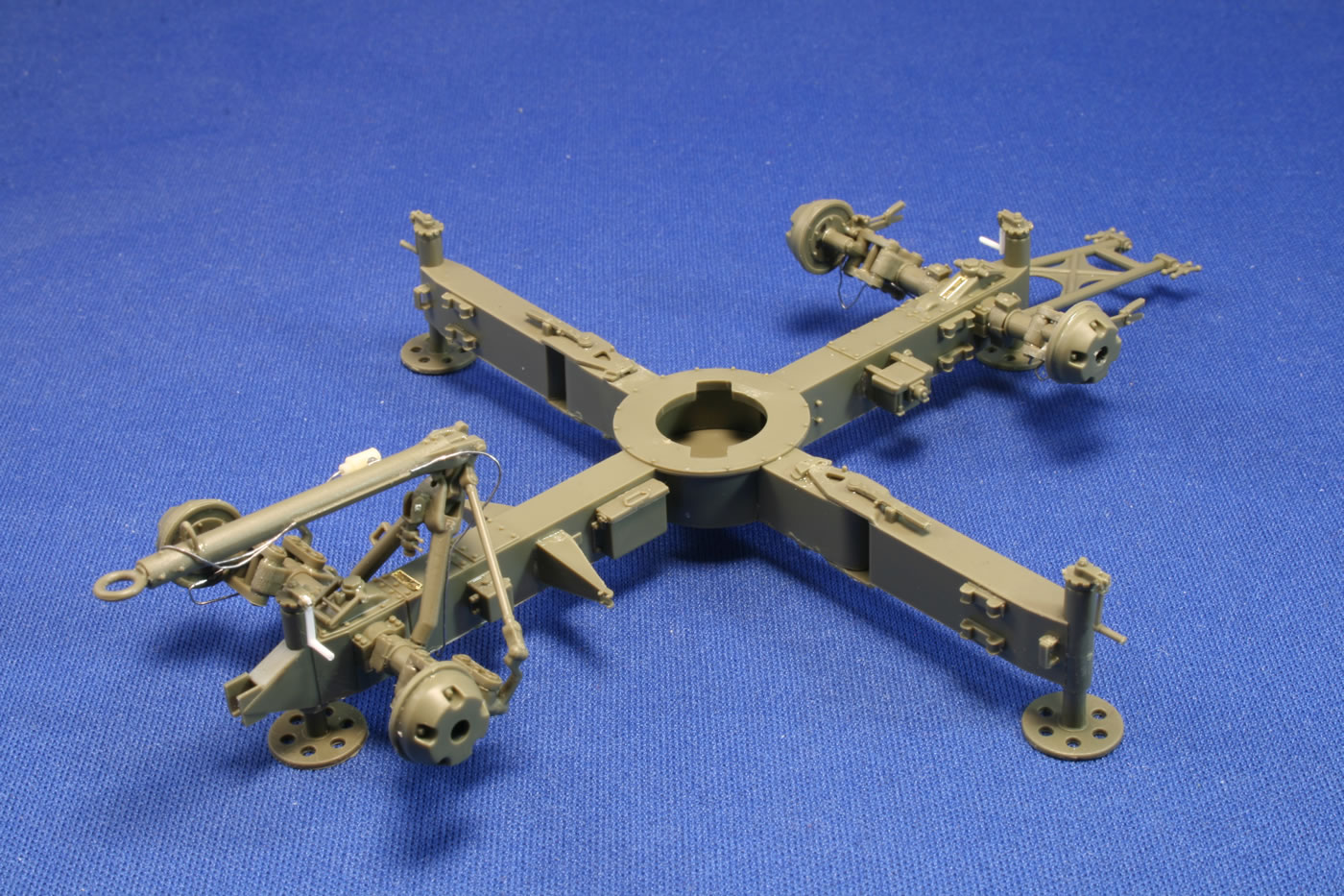
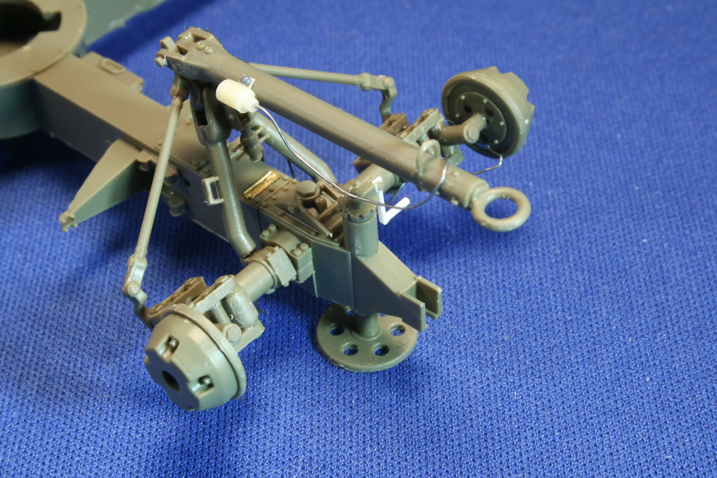
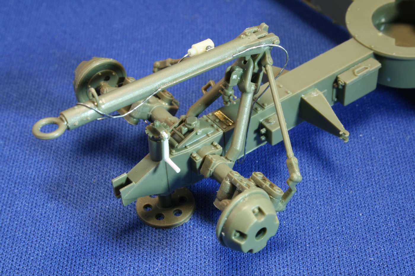
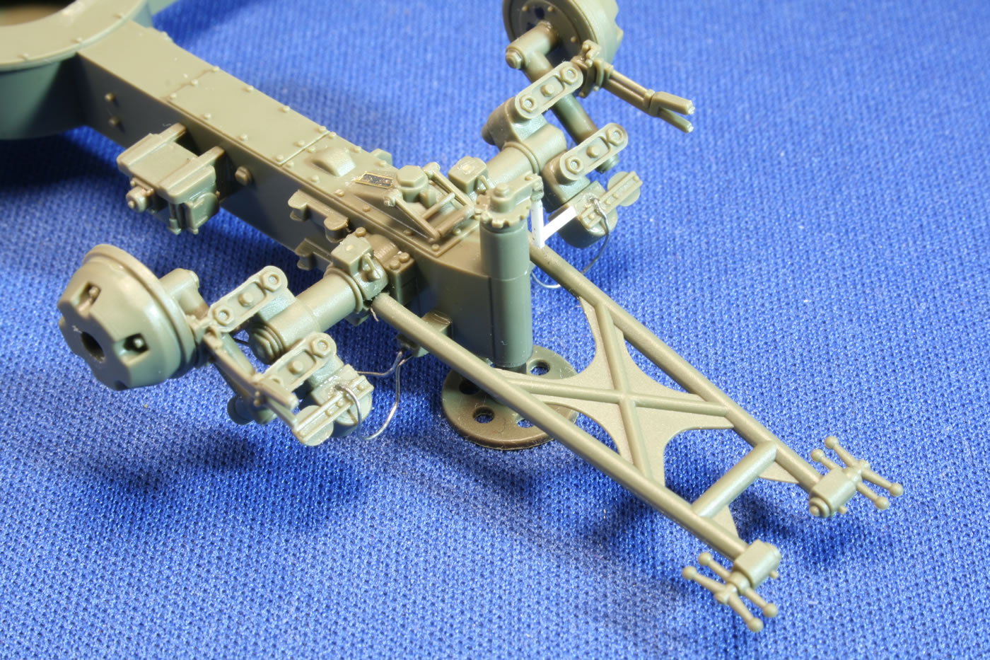
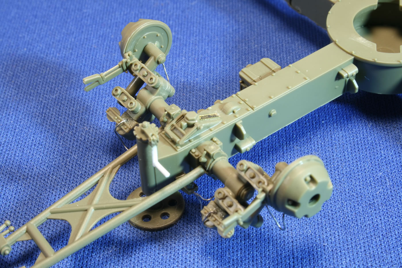
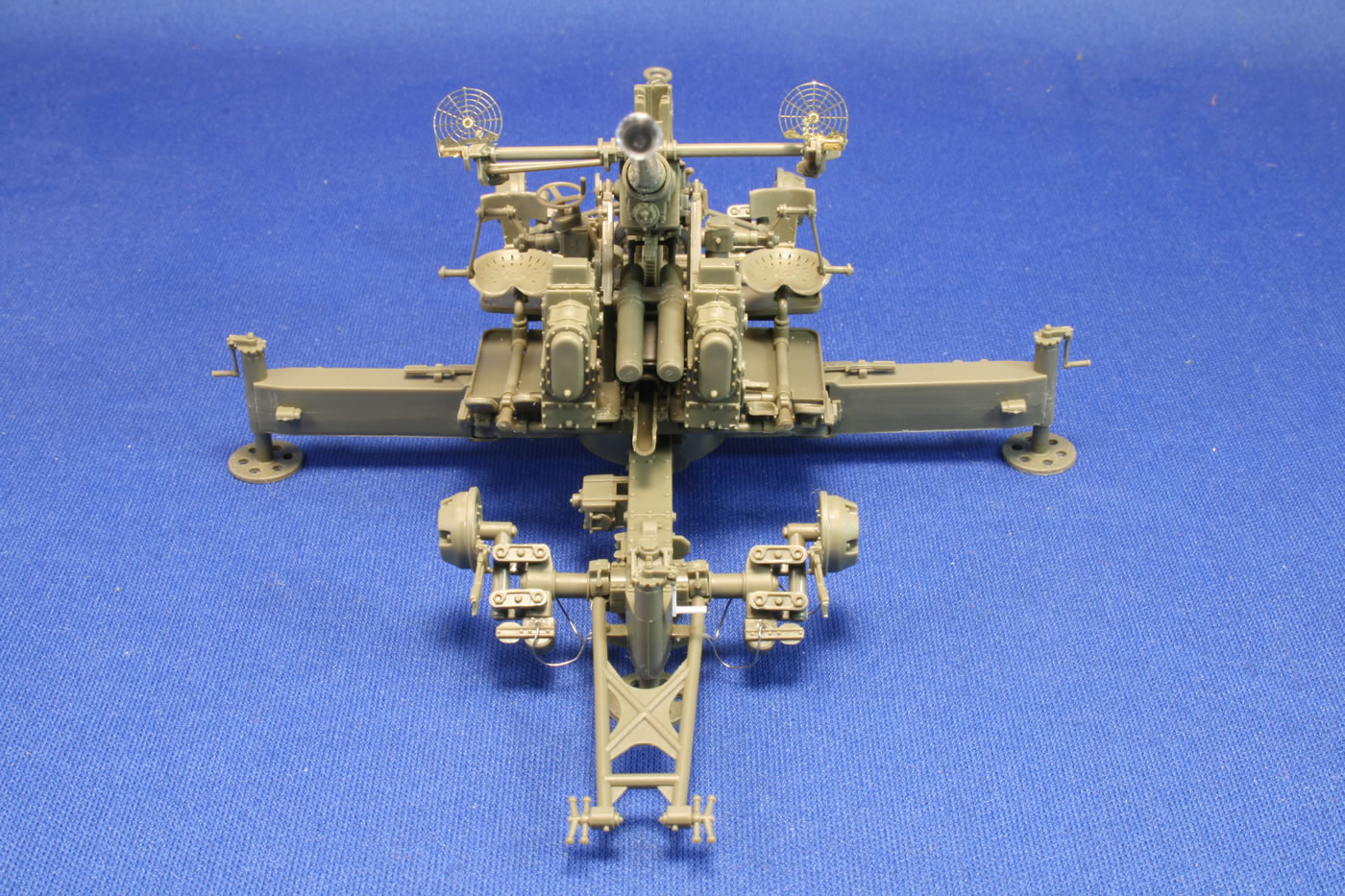
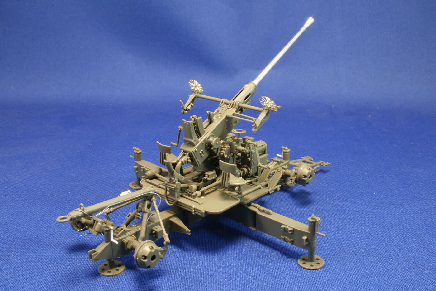
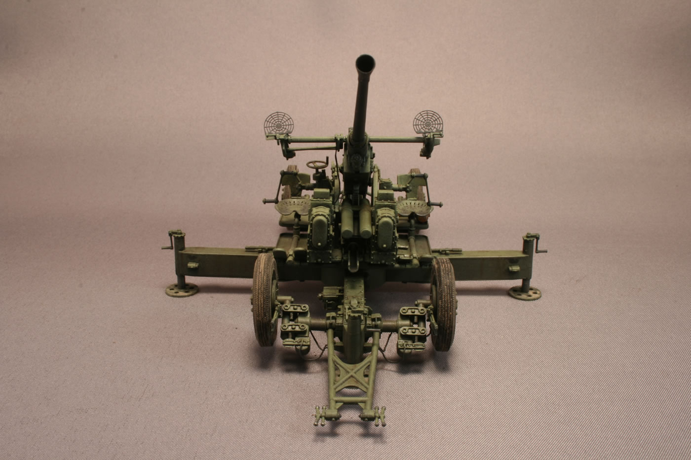
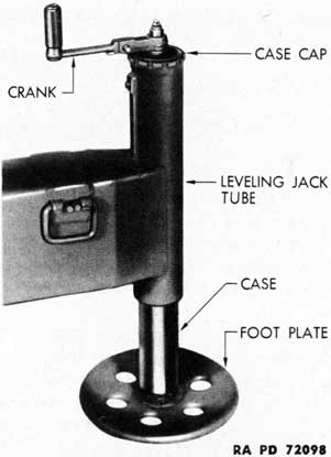
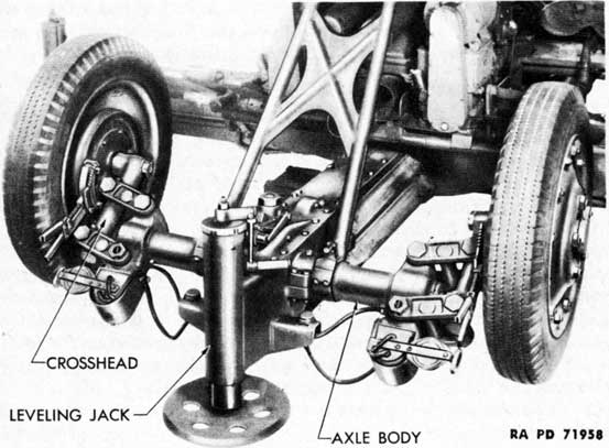
Club This kit presents AFV Club’s US version of the popular Bofors gun, which was fielded by numerous nations during WWII. Within a span of a couple years, modelers have been able to build British versions from AFV Club and Italeri, British and Canadian guns from Bronco, and a French variant from Hobby Boss. AFV Club has produced an intricate model that represents a later carriage than the one shown in TM 9-252, which is available online at http://www.hnsa.org/doc/boforstm252/index.htm. But this technical manual is especially helpful if you want to display the gun in its firing mode. The instructions are pretty straightforward if you want to build the Bofors for the road. The kit doesn’t give you any chance to waffle; right from the get-go, the first pieces in Step 1 should be set as shown in the instructions for the static gun, or flexed for the emplaced gun. So I suggest studying the manual images closely, and compare them to what the directions will be asking you to do. I’ll call out the more notable considerations. Step 1 beings with the assembly of the crosshead and axle body pieces. You’ll note when looking closely at the wheels raised in the emplaced position that these pieces are “flexed.” (This was something I hadn't noticed before glued these parts.) The instructions show the brackets (B8, B10) precisely parallel which is correct for the traveling arrangement. Step 2 begins with gluing two pieces (D21, D22) that serve as catches for the swinging outriggers when they extend. If you don’t glue them in the exactly correct spot, they won’t capture tips of the outriggers (pieces C19/C46 and C20/C47 in Step 7). You also capture a couple rubber sleeves in the main chassis. These trap the wheel axles in place. But AFV Club does a curious thing: the axle assemblies that were built in Step 1 are supposed to have their split ends mated inside the rubber sleeves. There is no real reason to make the axles spin-able, so I suggest considering gluing the axle ends as instructed, and if you are building the emplaced gun, rotating the assembled axles to the angled positions shown in the TM photos and gluing them in place with superglue. Make sure everything is square and aligned, particularly the joined axle. In Step 4, set the stabilizing stakes (B16) aside. Those were pounded into the ground, kept in place with parts D20. Also, set aside the foot pads (B5). These were adjusted by an elevating screw and hand cranks (D6 and the extremely fragile D19) to lift the gun off the wheels for firing. After dry fitting the wheels late in the build, I wasn’t satisfied how far the parts separated the wheels from the bench top, so I installed little 1/16 plastic rod spacers before gluing the foot plates in place. It’s important to make sure the chassis stays level if you are going to display your gun on a level surface like a plaque; it will also need to be level in a diorama, but you can fudge the groundwork.
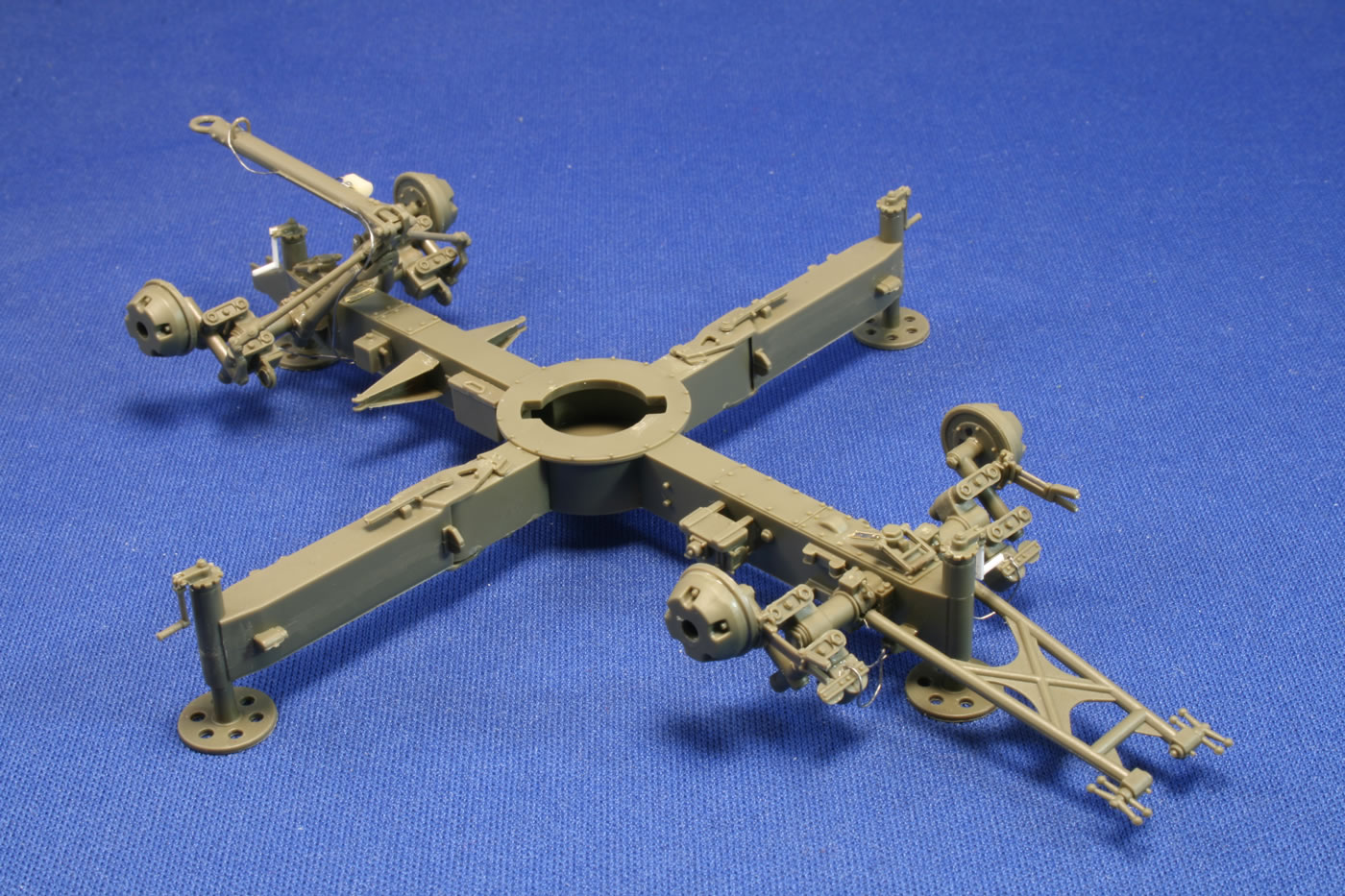
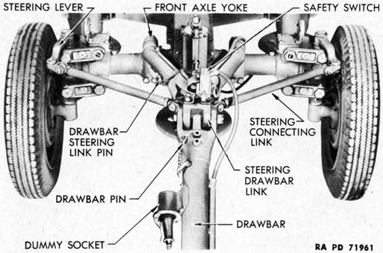
The instructions lose some clarity in Step 5, where it shows the axle lock handles and hand cranks for the elevation ratchets and can be positioned one way or another. Let the tech manual help guide you. I busted off the first two cranks I tried to glue, so I saved the other two until the very end of the build. Again, the manual is your guide with the drawbar (C12, etc.) and the gun stay frame (A71) in Step 6. The outriggers are the main feature in Step 7, as I indicated earlier. You can affix them to the chassis so they swing, but I’d suggest gluing them in your desired position: opened for firing, or closed for travel. I held off on gluing the wheels (D16) to the designated brake drums (D8). Instead, I dry fitted them to assure I got the right alignment when I glued the drums to the designated back plates and those pieces to the axle ends. Once the parts dried solid, I removed the wheels for easier painting and installation of the rubber tires.
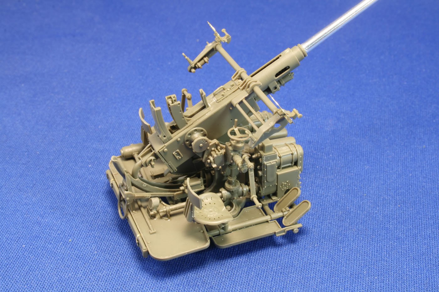
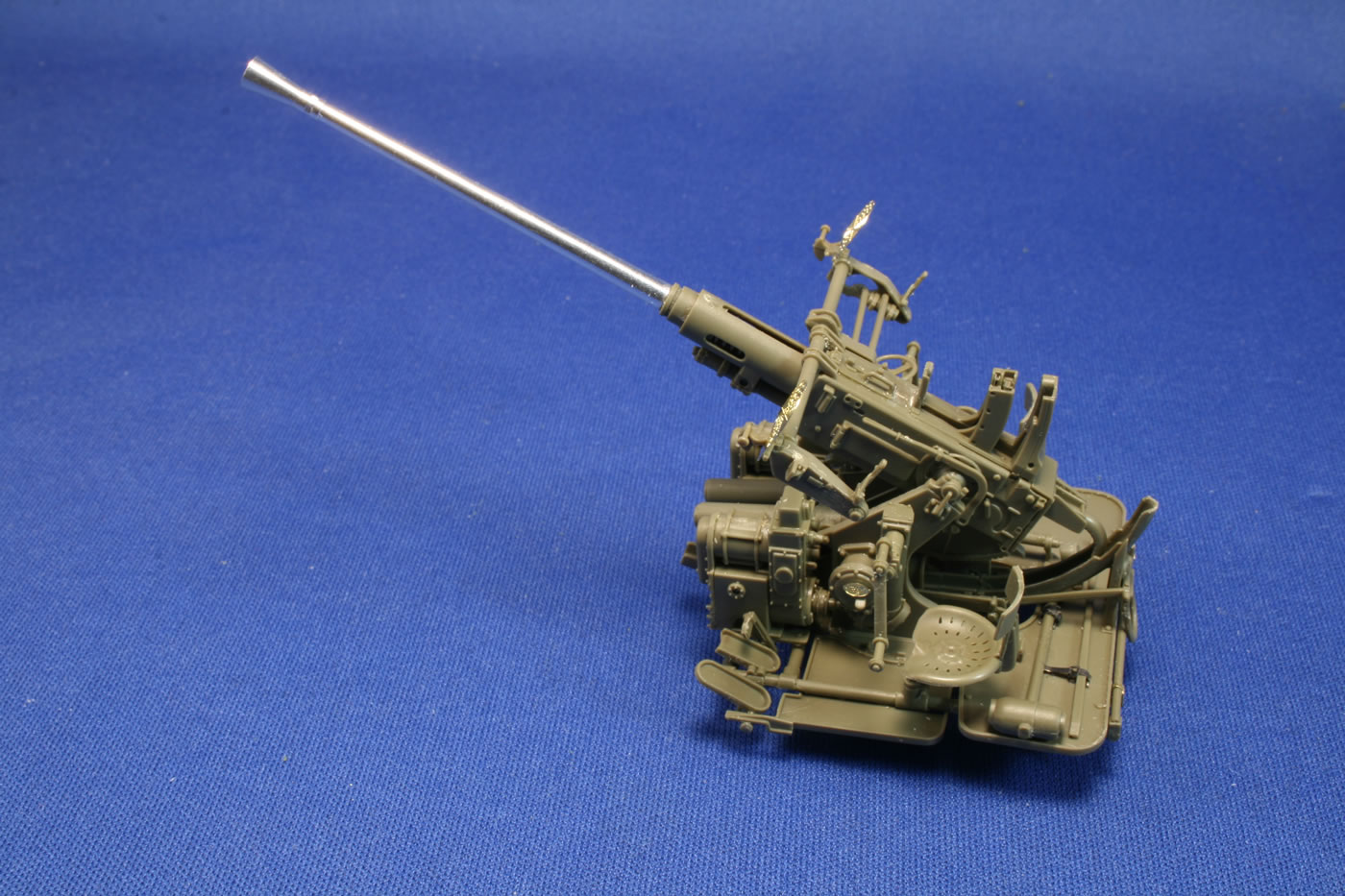
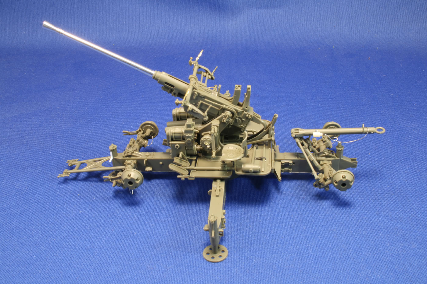
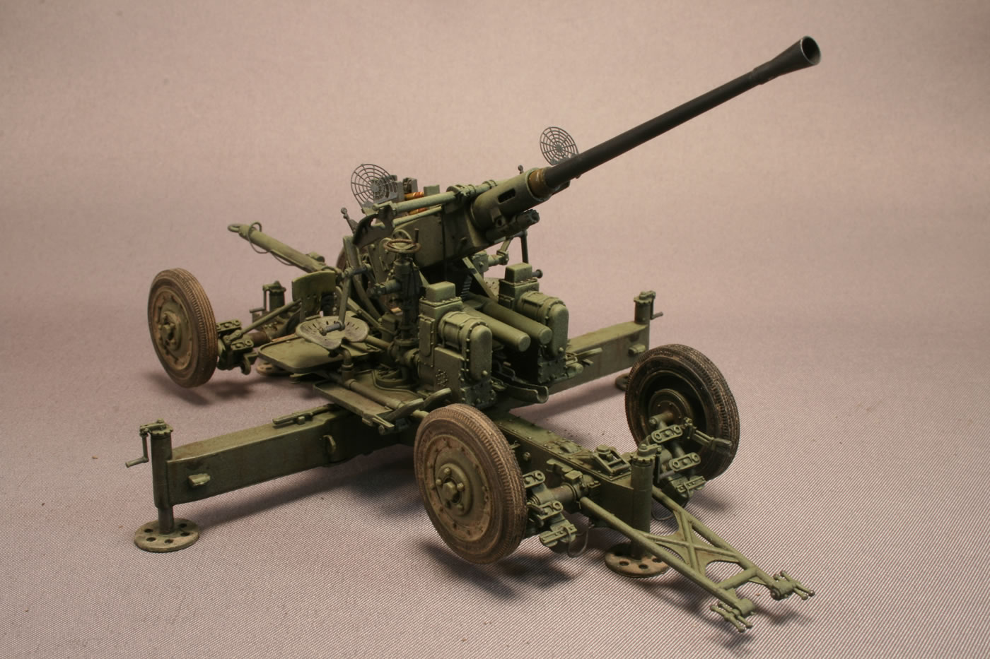
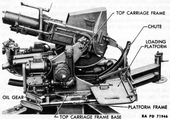
Take your time with the gun, especially the platform in steps 11 and 12. It helps to place a shim under the platform as shown in the photo, as there is a step up and you want your bracing to be properly squared. I don’t particularly like the kit’s photoetch straps because they don’t properly represent the strap threaded through the buckle. I used two, shortened, for the cleaning rod sections (A46) and pulled a couple spare Eduard straps for the tools since they include the footman loops. If I’d had some Aber buckles on hand I would have made my own with some foil. Things get a little tricky in Steps 17 and 18, with many very small parts for the hand operating crank mechanisms. Take your time here to keep the pieces properly aligned. I ended up trimming off a bit of piping to get one of the power units (assembly H) to sit properly on the platform.
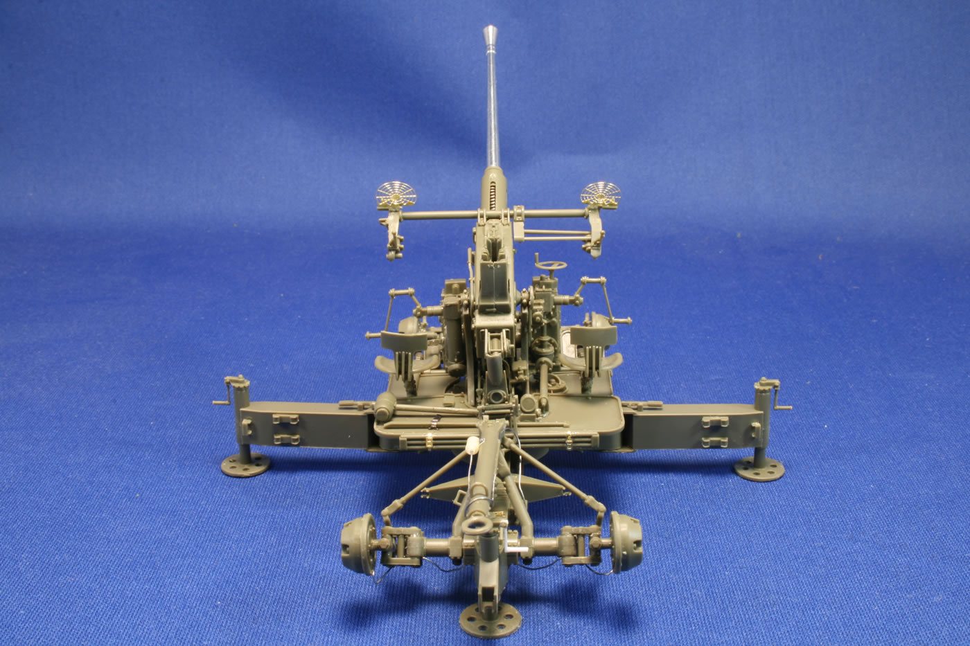
There are more small parts to handle with the gun sight assembly. I withheld the brass sights until after everything was done, including the adding lines for the brakes and lights which were created with .010 lead wire.
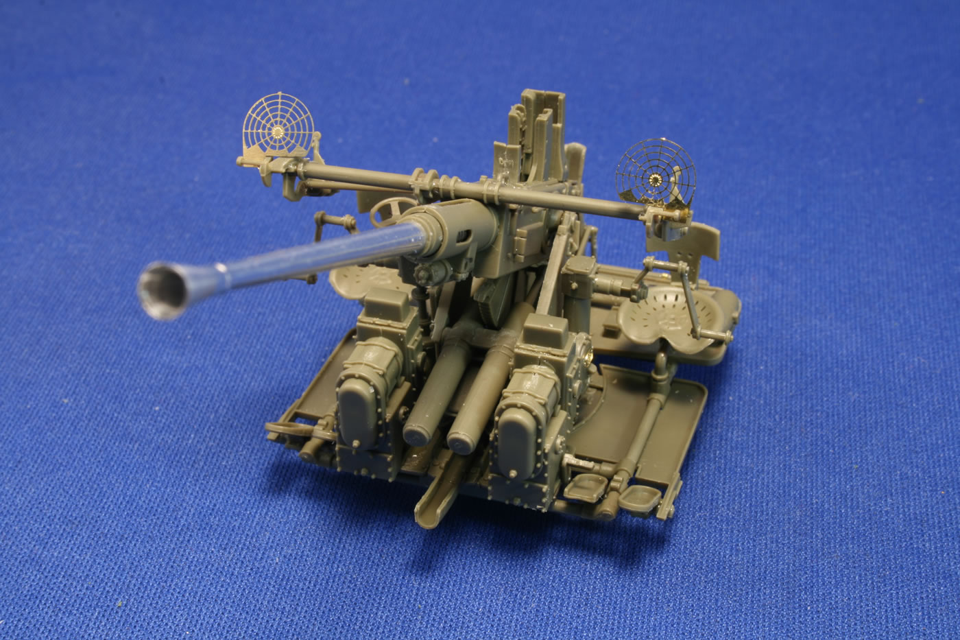
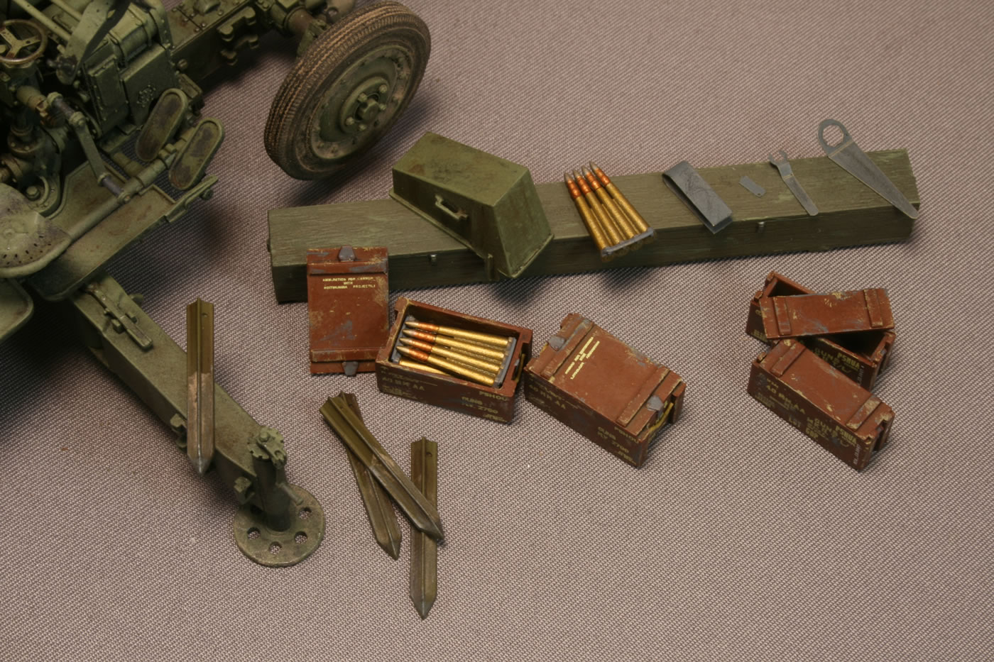
Overall, the kit goes together pretty well if you are patient and methodical. I was surprised to see some flash that I wouldn’t have expected from brand new molds, but it was minimal. Take care to remove the line seams even from the smallest pieces, as they will be apparent when painted. The kit includes a sprue of ammunition in charger clips and wooden boxes for the U.S. gun and British metal containers; see my separate review of the Ammunition and Accessory set and the brass amo set. One note is that the gun set includes decals with different markings for the eight-round box. The small fret of photoetch includes a large hub cap wrench, a smaller equilibrator rod nut wrench, a rectangular striker protrusion gauge, and cartridge remover. Review sample provided by AFV Club.
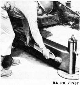
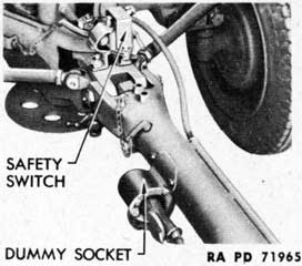
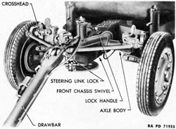
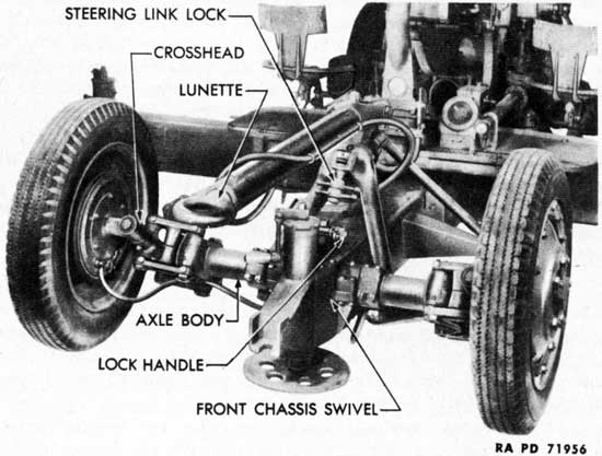
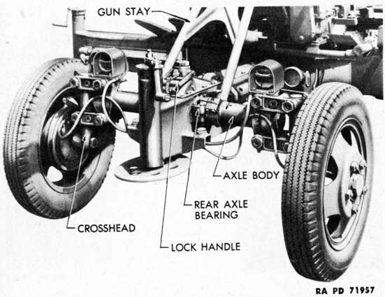
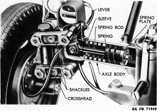
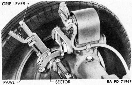
Here are some of the key illustrations from the tech manual.
-tss
|
 |
 |
 |
 |
 |
 |
 |
 |
 |
 |
 |
 |
|